
Solids and holes
How simple shapes become bores, slots and pockets, and how to change a group again later.
บทนี้ยังไม่ได้แปลเป็นภาษาไทย เนื้อหาด้านล่างเป็นภาษาอังกฤษ
This is the most important idea in layerling, and it is quickly learned: Every shape is either a solid or a hole. A solid stays. A hole is a tool that takes material away.
Solid or hole
Select a shape and click “ชิ้นตัน” or “ชิ้นเจาะรู” in its settings. The keyboard is faster: H makes the selection a hole, S makes it a solid again. Both are also in the menu a right click on the body opens. A hole is shown see-through so you can see where it sits. T makes a body see-through, say to look into a housing; a second press makes it opaque again. It works on the whole selection: if any body is already see-through, all become opaque, otherwise all become see-through.
As long as nothing is grouped, nothing happens with a hole. It just lies there and shows where something will disappear later.
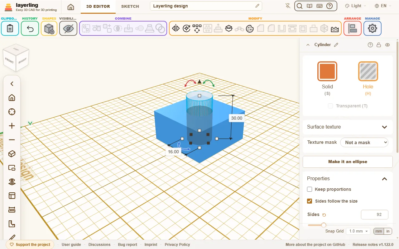
Grouping
Select solids and hole(s) and click “รวมกลุ่ม” (Ctrl+G). Now the holes remove the material from the solids they touch. What remains is one single new shape.
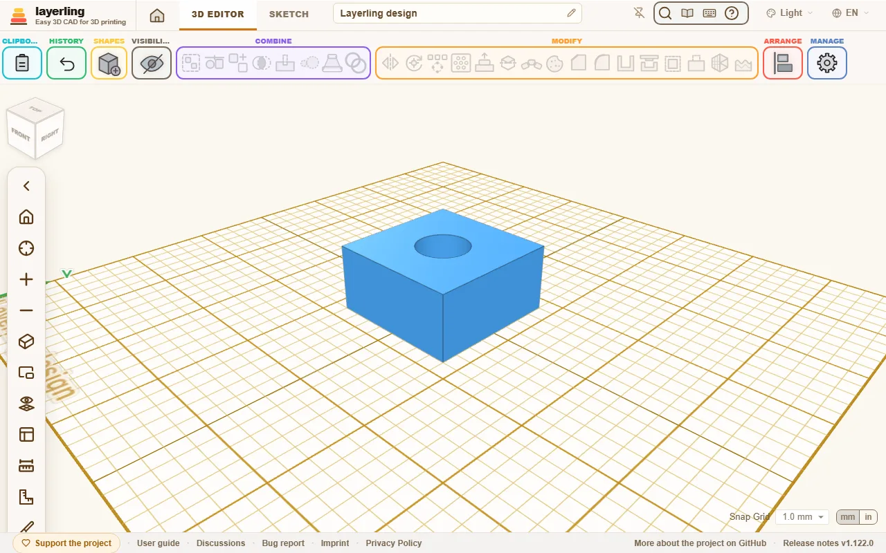
This is how you get:
- Bores: a cylinder as a hole through a body.
- Slots: an elongated box as a hole at the edge.
- Pockets: a hole that does not go all the way through.
- Threads in a part: a tapped hole as a hole, see Threads and mechanics.
If several solids are in the group, they are joined. Two solids that touch become a single part.
With large meshes, such as an imported STL with hundreds of thousands of triangles, the cut takes a few seconds. layerling then works in the background and shows "“กำลังคำนวณ… ทำงานต่อได้เลย”"; meanwhile you can turn the view and use the interface. If you change the scene in that time, the result is dropped and layerling tells you so. The same goes for “ผ่าชิ้น”.
You can treat a group like a shape: move, rotate, colour, group again. “แยกกลุ่ม” (Ctrl+Shift+G) dissolves it and the individual parts are back.
Making a group a hole
A whole group can also be a solid or a hole. A simple rule applies:
- If the group consists only of solids (or only of holes), you switch it as a whole and its parts go along.
- If it contains both, say a cube with a bore, each part keeps its own state. The whole group then becomes a tool, but the bore stays a bore.
Resizing a group: keeping holes and small parts
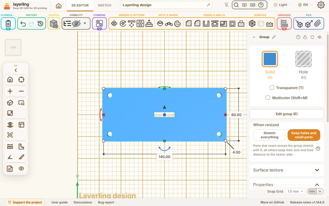
When a group is made longer, wider or taller, its parts stretch with it as if they were drawn on rubber: the round holes in a plate become ovals and move inwards. To keep them as they are, choose “คงขนาดรูและชิ้นส่วนเล็ก” under “เมื่อปรับขนาด” in the group's settings; “ยืดทุกอย่าง” is what every group does until you change it. From then on, each time the group is resized - with the handles, the size fields or “ย่อ/ขยายเป็นเปอร์เซ็นต์” - it is built again from its parts by one rule, along each direction on its own:
- A part that reaches across nearly the whole group, nine tenths of it or more, grows or shrinks with it and keeps its distance to both sides: the plate itself, a wall, or the inside of a box, whose walls stay as thick as they were.
- Every other part keeps its own size and its distance to the nearer side. A part in the middle stays in the middle.
So a plate with a hole 5 mm in from each corner and a slot in the middle, made 40 mm longer, keeps its holes round and 5 mm from the corners, and the slot in the middle. There is no solver behind it and nothing to set up part by part: the same rule holds for every part, so you can tell beforehand what will happen. A turned part counts with the box it takes up in the group and stays turned; a group inside the group counts as one part. While you drag a handle, the group stretches as a whole; when you let go, it is built again, in the same undo step. Made smaller than a part needs with its distance, that part shrinks with the group as before, and a message says so. A mirrored, tapered or twisted group, and one with fillets, chamfers or a texture of its own, always stretches everything. Chosen for a group that is stretched already, the setting lays its parts out again at once.
Bundling
Sometimes parts should only stay together without becoming one - a white logo on a black plate for a multicolour print, say. That is what “มัดรวม” (Ctrl+B) is for, as in Tinkercad. A bundle moves, turns and resizes like a shape, but nothing is merged:
- Every part keeps its colour and stays a solid or a hole. The bundle's settings have the same cards as a group's: “ชิ้นตัน” and “ชิ้นเจาะรู” for the whole bundle (which keep the parts' colours), “โปร่งใส” (T) and “หลายสี” (Shift+M); with Multicolor switched off the bundle shows and exports in one colour. “แยกชิ้นส่วน” takes the bundle apart, as Ctrl+Shift+G does.
- Holes cut nothing. When you group the bundle with other parts, its holes cut those parts but still not the bundle's own solids, as in Tinkercad. So a peg with its hole beside it, say, can be used again and again as a bundle.
- In an STL, 3MF or OBJ export every part is a body of its own; in 3MF and OBJ with its colour.
“แยกกลุ่ม” (Ctrl+Shift+G) takes a bundle apart again, E opens it for editing like a group. Chamfer, fillet and hollowing do not work on a bundle, because it is not one body: group it for that, or work on its parts one by one. If a hole in the bundle should cut the bundle's own solids too, take the bundle apart and group its parts (Ctrl+G).
Intersection
“เอาเฉพาะส่วนที่ซ้อนกัน” keeps only what two or more bodies have in common. Lay two overlapping shapes on top of each other, select both and click it. That turns a cylinder and a box into a piece with one round and one straight side. A group counts the way it looks, holes included. If a hole is selected too, what remains is what all the solids share with all the holes. If the shapes share nothing, nothing is changed and a message says so. The first click shows the common part before it is applied: the selected shapes turn see-through and what they share is drawn in green. Select and move each shape on its own and the green part follows; a second click on “เอาเฉพาะส่วนที่ซ้อนกัน” applies it, Esc closes the preview. Shapes with too many triangles for the preview, such as large imported meshes, are intersected on the first click.
“ห่อรวม (Hull)” wraps the selected shapes in one convex body, as if they were shrink-wrapped: the smallest body without dents that holds all of them. A half sphere on a cylinder becomes a dome with no step, four cylinders at the corners become a box with round corners, two spheres a capsule. Holes in the selection are cut out of the hull afterwards. The parts stay in it: “แก้ไขกลุ่ม” opens the hull like a group, and moving a part there and closing it builds the hull anew. The hull is a mesh, so round shapes show facets, and the edge tools work on it as on any mesh. When only holes are selected, the hull is a hole itself: two cylinder holes cut a slot. A hull fills whatever is hollow in its parts: a tube, a cylinder hollowed with “ทำกลวง”, a part grouped with its holes. Switch on “คงรูของชิ้นส่วนไว้” under Properties to keep them open: the hull then only fills the space between the parts, and a recess at the side of a part stays as well.
“พิมพ์กดคุกกี้” makes a cookie cutter from the selection: a thin wall round the outline, standing 15 mm high, and a flat rim of 2 mm round its foot, so the cutter stands on the rim and a thumb has something to press. Select one imported SVG or one sketch body and its own outline is used. A text lying flat gives its letters' own curves. Any other shape, a built one, an imported mesh or several parts, gives what it stands on: the outline the workplane cuts through it, so put it on the workplane first. Parts that overlap give one outline round all of them, as if they were grouped; parts apart from each other give a cutter each, in the same bundle. The outline is mirrored left to right: the cutter is printed standing on its rim and turned over to cut, so a text or a logo comes out the right way round on the dough. The wall's top runs in to a cutting edge 0.4 mm wide. Holes in the outline, the inside of an e or an a, get walls of their own, so they are cut out of the cookie too. They are a body of their own in the bundle, “ผนังด้านใน”: to have a text or a pattern only pressed into the dough instead of cut out, make them lower under Properties. With a wall of 15 mm and dough 5 mm thick, inner walls of 12 mm press 2 mm deep. Inner walls lower than the outer wall have a flat top instead of the cutting edge: they only press, and an edge would leave thin tips that break off and grooves that hold dough. Give them an edge under Properties if you want one. Two bridges at the rim, on the side your hand presses, hold each inner wall to the wall round it, spread round it, 4 mm wide and 3 mm high. Each bridge stands with its whole width on the walls, in the middle of a side that runs along the outline, and never across another piece. Pieces side by side, such as the letters of a name, are also joined to each other, the closest first, so the bridges run as a web through all of them and a letter in the middle of a word is held as well. A click on the tool opens a small window: there you choose a “แผ่นฐาน” instead of the bridges, which fills the whole outline on the side you press, is steadier and sticks better to the print bed, but no longer lets you push the dough out from behind. “ลบมุมโค้ง” puts small 45° slopes where the walls stand on the rim, the bridges or the plate, so thin parts such as the dot of an i do not break off; they are a body of their own in the bundle. There you also set how much lower the inner walls are and whether the outline is mirrored; the values stay for the next cutter. Change their height under Properties like the rim's. The cutter replaces the selection as a bundle of sketch bodies, “แก้ไขกลุ่ม” opens it. Wall, inner walls and rim are the sketch fill modes, a line outside the silhouette: change the thickness, height or colour of each under Properties, and the wall's “คมตัด” there too (0 for a flat top). Where a tight bend leaves no room for a chamfer on both sides, the wall is bevelled on its outside only, to the same edge. Where an outline cannot be chamfered at all - a logo with sharp points, an outline cut from a body's triangles - the edge is built in fine steps of 0.1 mm instead, which a print layer of 0.2 mm cannot tell from the slope; such a wall is a triangle mesh rather than an exact body. To keep the outline as drawn, mirror the cutter back with “สะท้อน”, “ซ้าย-ขวา”. A PNG or JPG picture works too: imported, it is traced into a sketch body, and the cutter follows that one.
“เชื่อมสเก็ตช์เป็นชิ้น” joins two sketch bodies or imported SVGs into one body: the outline of the lower one at the bottom, the outline of the upper one at the top, with straight walls between them. That makes a funnel, a transition piece from square to round, or a frame that narrows towards the top. Put the two bodies one above the other where they belong, shifted and turned if you like, select both and click the tool. The loft reaches from the bottom of the lower body to the top of the upper one.
Each of the two needs exactly one outline. If it has a hole, a ring say, the other needs as many, and the holes are lofted too: two rings give a hollow wall. A sketch built as a line (a line outside, inside or centred under Properties) counts as such a ring. An imported SVG comes in filled; to make it a ring, give it a line under Properties. Both bodies must lie flat; the tool refuses tipped ones.
The loft is an exact CAD body; the edge tools and the STEP export take it as one. The two sketches stay inside it: “แก้ไขกลุ่ม” opens them like a group, and moving or changing one there, or editing its sketch, and closing it builds the loft anew. “แยกกลุ่ม” sets the two sketches free again. For two rectangles, circles or polygons there is also the Loft shape among the shapes, whose ends you set as numbers.
Cutting one body out of another
For parts that have to fit, a shaft in a collar, a bolt in a case, you make the one part and cut it out of the other. Select the two bodies and click “เจาะตามรูปชิ้น” in the “รวมชิ้น” area, or right-click and choose it there. The tool window names the part that stays and the body that gets the cavity; layerling takes the smaller one as the part, and a click on “สลับสองชิ้น” turns it around. The “ระยะเผื่อ” makes the cavity that much larger than the part on every side: 0 fits exactly, 0.2 mm is a usual room for a printed fit. “เจาะ” cuts a copy of the part out of the other body and leaves the part itself where it is. The result is a group: “แยกกลุ่ม” takes the cut apart again. A clearance needs the part to be an exact body, like the “ขยาย/หดผิว” tool, which it uses.
Punching an outline through a body
To cut the outline of one body straight through another, select the punch first and then the body to punch, and click “เจาะทะลุ” in the “รวมชิ้น” area, or right-click and choose it there. The two need not touch: the punch can stand anywhere in front of the body, and only its outline seen along the “ทิศทาง” counts, so a teapot held over a plate leaves a teapot-shaped opening. layerling starts with the axis along which the punch stands furthest from the body; X runs left to right, Y front to back, Z up. “สลับสองชิ้น” turns the roles around, and the “ระยะเผื่อ” makes the opening larger on every side, 0.2 mm for a printed part that has to pass through. “เจาะ” groups the opening with the body as an exact sketch body set to hole, so “แยกกลุ่ม” takes it out again; the punch stays where it is. Move or turn it and punch again for another opening.
Editing a group
If a bore turned out too small, you do not have to dissolve the group and rebuild. Select the group and click “แก้ไขกลุ่ม” in its settings, the folder icon in the object list, or press E. In the object list you can also open the group with its arrow and click one of its parts: the group opens with that part selected. A double click on the group does the same, as in Tinkercad, on a bundle too; if you would rather not, switch off “ดับเบิลคลิกเพื่อเปิดกลุ่มหรือชุด” in the settings. A part only starts to move once the pointer has been dragged a few pixels, so a shaky click or double click does not nudge it. The parts now lie separately and you change them with every tool: make a hole larger, move a body, add a hole.
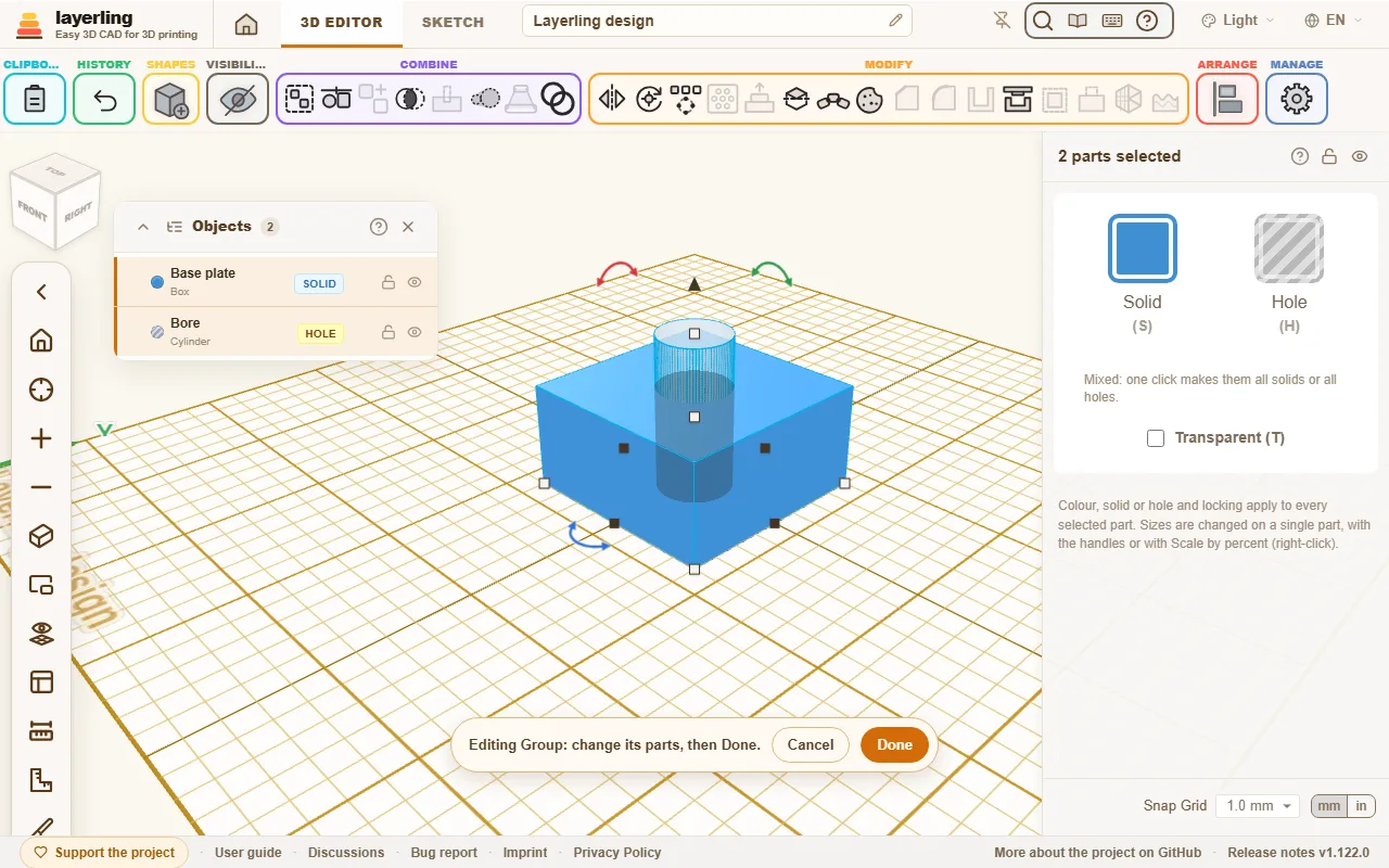
A bar appears at the bottom of the picture. “เสร็จ” rebuilds the group, with its name, its colour and its state as solid or hole. “ยกเลิก” puts it back untouched.
If one of the parts is itself a group, you can edit it the same way, and so on as deep as your design goes. The bar shows where you are, for example "Bracket › Screw boss". “เสร็จ” and “ยกเลิก” always finish the innermost group and take you one level back out. While you are inside a group, only the groups among its parts can be edited; to edit another one, finish first.
Unlike “แยกกลุ่ม”, which takes a group apart for good, editing keeps the group: its name and settings stay, and you can always go back with “ยกเลิก”.
A note: fillets and chamfers you had put on the whole group are lost on rebuild. The bar tells you so.
Splitting
“ผ่าชิ้น” in the “ผ่าชิ้นและปรับรูปทรง” area cuts the selection in two with a plane - a part too big for the print bed, say, or one you want to see the inside of. Select one or more solids or holes and click it. A translucent plane shows exactly where the cut will go, and a white line marks it on the bodies themselves, where the plane meets them; nothing changes until you apply it.
- “ทิศทางของระนาบ”: X makes an upright cut between left and right, Y between front and back, Z a horizontal cut between top and bottom. The axes are named as on the Position card, with Z up. The plane starts parallel to the workplane, so on the base plate with Z.
- “จัดแนวตามพื้นงาน”: “ขนาน” lays the plane parallel to the workplane, “ตัดขวางแกน X” and “ตัดขวางแกน Y” stand it square to it, across its X or Y direction. Where the workplane's origin crosses the selection the plane goes through it, otherwise through the middle. On the base plate “ตัดขวางแกน X” and “ตัดขวางแกน Y” always go through the middle of the selection, as the middle of the plate has nothing to do with the parts. So you put the workplane on a sloped face with W and cut right there, without turning the sliders.
- “ตำแหน่งระนาบ”: where the plane crosses, with the slider or typed in. It starts in the middle. You can also drag the arrow head on the plane; the plane moves along the arrow in 0.1 mm steps.
- “เลือกหน้า”, the button next to the position, lays the plane on a face: click it, then click the face. Orientation, both rotations and position are set to match. While you pick, a blue plane under the pointer shows the face it will take. A face of a body that is not selected works too, to line the cut up with it, but the plane stays within the selection. Esc stops picking and leaves the plane where it was.
- The two rotation sliders below turn the plane about the other two axes, up to 180° either way, for an angled cut. They can be combined.
“ผ่าโมเดล” or Enter makes the cut, Esc cancels (while picking a face, the first Esc only stops picking). Every object the plane crosses becomes two closed bodies, named after their side, for example "Box (Z+)" and "Box (Z-)"; objects it misses stay as they are. A hole becomes two holes, and a hollowed body keeps its cavity. Both halves stay where they were - for printing, lay each one on its cut face with “วางราบตามหน้า”.
“ตัวเชื่อม” line the halves up again, as the cut tools of PrusaSlicer, OrcaSlicer and Bambu Studio do. With “ไม่มี”, the default, the split is as described above. “เดือย” makes a hole in each half and loose pins that go into both: the pins come as a third body, standing beside the halves on their floor, to print with them - standing, they come out round in the layers as their holes do, which is what the fit test measures. “ปุ่มเสียบ” stands round pegs on the half whose name ends in a minus, with the holes for them in the other half. The connectors go in square to the plane, however it is turned, each with its diameter and 1.2 mm of material to every edge of the cut face, and two of them twice that apart. Each separate piece of the cut face gets its own, spread evenly over it: “ต่อหน้าตัด (0 = อัตโนมัติ)” says how many, and 0 leaves it to the piece's size, with at least two. A piece too small for one gets none, and a connector is left out where a half is thinner than its hole is deep; the panel says so before you split, and white rings on the plane show where they will go. If none fits at all, the parts are split without, and the status bar says so.
- “เส้นผ่านศูนย์กลาง” is that of the pins and pegs, 5 mm to begin with.
- “ความลึกเข้าไปในแต่ละครึ่ง” is how far each hole goes into its half. A dowel is twice that less 0.6 mm long and a peg 0.3 mm shorter than its hole, so they never stand on the floor of a hole and the halves close fully. Pins and pegs have a small chamfer at their ends, and each hole one at its mouth, so a first layer that spread does not narrow it.
- “เดือยบนฐานแบบหักออก”, with “เดือย”, stands the loose pins on one plate that holds on to the bed, for a printer whose bed moves and makes standing pins wobble loose. Each pin rests on a small nub in a socket of the plate; once printed, bend each one to and fro to snap it off, as the fit test's pin can be.
- “ระยะเผื่อต่อด้าน” is the room between a pin or peg and its hole. Once you have measured your printer's play with the fit test (in the chapter on printing), it starts from that, otherwise from 0.2 mm.
“หางเหยี่ยว” holds the halves together without glue, like the dovetail cut of OrcaSlicer: a tongue that widens away from the cut face stands on the half whose name ends in a minus and runs straight across it, from edge to edge, and the other half gets the matching groove, open at both ends. Slide the halves together from the side, along the tongue; once in, they cannot be pulled apart across the cut. The tongues run the long way of the cut face, and where a body meets the plane in several pieces, they run the same way on all of them, so a half slides on in one move. “ต่อหน้าตัด (0 = อัตโนมัติ)” is the number of tongues side by side on each piece; 0 leaves it to the piece's width, one for every six tongue widths, at least one. Beside its wide top a tongue keeps half its own width and another 1.2 mm of material to the edge of the cut face, and two tongues twice that apart. A piece too narrow for one, or too short along it, gets none, and a tongue is left out where the other half is thinner than its groove is deep. White outlines on the plane show where they will go: the filled strip is the tongue's foot, the line about it its wide top.
- “ความกว้างที่หน้าตัด” is the tongue's width where it leaves the cut face, 6 mm to begin with.
- “ความลึกเข้าไปในอีกครึ่ง” is how far it stands out of the cut face into the other half, 4 mm to begin with. The groove is 0.3 mm deeper, so the halves close fully.
- “มุมด้านข้าง” is how far each flank leans out from square to the cut face, from 5° to 30°, 15° to begin with. The larger it is, the wider the tongue's top and the firmer it holds.
- “ทิศทาง (0 = ตามแนวยาว)”: 0 runs the tongues lengthwise, 90 across the cut face, and an angle between turns them that far.
- “ระยะเผื่อต่อด้าน” is the room on each side between the tongue and its groove, from your fit test as for the dowels. The tongue's ends are chamfered all round so it finds the groove, and the groove has a chamfer at its mouth.
For printing, lay the half with the groove on its cut face, and print the half with the tongue the other way up, its cut face on top: the tongue's flanks then lean out by no more than their angle, which prints without supports.
Holes are split without connectors.
“ยืด” at the top of the panel, beside “ผ่าเป็นสองชิ้น”, makes the selection longer at the plane instead of cutting it in two - a case downloaded without its CAD file whose compartment should be longer, say. Place the plane as for a split, through the part that may grow, and type “ยาวขึ้น (ติดลบ: สั้นลง)”: the part on the side the arrow points to moves that far away, and the cut through the body at the plane, drawn out over that length, fills the gap. Straight walls and floors get longer; compartments, rounded corners and holes on either side keep their size. A minus value makes it shorter: a slice that thick comes out on the arrow's side and the rest moves back. “ยืด” applies it; every object the plane crosses stays one closed body under its own name, a mesh like the halves of a split. Where the plane runs through a slanted or round part, its cut is drawn out straight, so place it where the body runs straight.
The halves are plain meshes: settings such as a cylinder's sides or a text's lettering are gone, so set those first. Ctrl+Z brings the original back in one step. Locked and hidden objects cannot be split.
An imported mesh needs a closed surface to be split, grouped or cut. If it has openings, such as the eyes of a figure left open or a crack in a scan, layerling closes them with a flat cap first and says how many it closed. It closes small openings and flat ones of any size; a large opening whose rim bends is left to you, and the message says so. Close it in the program the model comes from, or with a mesh repair tool, and import it again.
Separating parts
If a shape consists of several separate pieces, such as text made of single letters, “แยกชิ้นส่วน” splits it into independent shapes. The entry is also in the menu you get with a right click on the shape.